Saturday, 16 October 2021

Before/After

I thought it would be a good idea to compare the new case with the old one. So here it is.

Before :

After :

More space, better power supply, better ergonomics overall.


Sunday, 3 October 2021

Tiptop Mantis

Close up of the new case


My synth suitcase is very cool.  I enjoyed setting up the inside of the case, spending hours building modules and experimenting on my first patches.  
Final shot of the synth suitcase

But, with the last modules I bought (some of them still to be revealed), it became too small. Also, I reckon the power supply is at its limits.  I find that it starts to heat up too much during long sessions.  Finally, the fact that I don't have a removable lid makes it a bit uncomfortable to use.  Although I have used it a few times as a stand for the sequencer or an additional Volca, it's not very convenient to have the lid in the way.

So I decided to buy another modular synthesizer case.
The Mantis from Tiptop Audio is elegant, widely recommended, of a manageable size and not too expensive.
Assembly, following my Modular Grid plan on my phone

Bob pulls the module

Internally, there is a comfortable power supply (more than twice the power of my previous power supply) with shrouded connectors.  
Some of these connectors are mounted horizontally, freeing up space at the bottom of the case (61mm deep at most).
Not enough space

Despite this, there is not enough space for my deepest modules: in the top part modules cannot be deeper than 50 mm. My sample&hold can hardly fit in there because what is sticking out can slip behind the bus board.


Also, the feet take up some space, which drastically limits the depth of the modules on the left and right of the bottom row. 


I had to revise my plans by inverting the two rows in relation to the synth-valise. For the better I think.  Anyway, no other choice.


I thought I was indifferent to having threaded rails or sliding nuts. Or even that I liked the fact that I could quickly reposition modules with the sliding nuts. I was wrong.  The threaded rails are much more practical.  The assembly went smoothly.  I just had to plan to run two power cables from the bottom modules to the second row, as there is only room for 12 horizontal connectors and there will be 13 modules in the first row.

Bob plugs the cables

Finally, being able to position the box at 45° is a real space saver and is ergonomically pleasing.  On the other hand, at 90°, I am not confident enough in the two plastic legs.

The cable of the external power adapter is too short. The 230V power cord can be changed easily.  But the connection to the box could be 2x longer.  If you want to have the box vertical, the power supply hangs down and it's a shame.


Oscillators, filters, resonator

No sound example today.   But a quiz: a new module has slipped into the set, can you spot it?
The answer will be the subject of the next article.


Friday, 28 May 2021

Passive Modules

Finished guys
It looks like it has been a year since I built my last DIY module.
Time for some passive modules I guess.

I ordered two 2-hp blank.  I needed another multiple to fill the rack and I decided to experiment with some passive functions.


A passive multiple is very basic.  You simple connect the tip and ground of each jack.  In practice the ground connection is established via the aluminium panel.  No need to use wire.

The main difficulty here is at 2-hp, or a bit more than 1 cm width, you do not have a lot of margin to drill your holes.  You do not want the body of the jack to go over the edge.
Not perfect but good enough.
I used mostly very cheap jacks I got a long time ago, except for the one with the switch as the switch on the cheaper ones is really terrible.

Behind the scene


Bob at work with the panel
I also experimented with some minimal panel marking by using my Dremel to carve some traces and fill them with a permanent marker.  This should not age very well. Time will tell.

The second module is the combination of a passive OR and a half-wave rectifier, ideal to combine gates and manipulate control voltages or distord audio.  You’ll find  the layout for both of them at the end of the article.  I got the schematics from unrecordings! blog

In the rack

In the following piece, the Korg SQ-1 produces two tracks of gates and CV for the kick and hi-hat.
I used the multiple to distribute the gates everywhere in the synth and I used the OR function to build a third melodic track from the first one and the output of the Turing Machine,  clocked by the second track.  I know it sounds complicated.  Patch schematics is at the end of the article.
The half-wave rectifier produces some overtones to spice up the sounds.
The variations in the piece is me playing with the sequencer.


Connection layout


Patch of the day

Sunday, 11 April 2021

Emilie's Last Stand

So I got Beads.

Not the decorative string of pearls, the Eurorack Module from Mutable Instruments.

To be more specific, Beads is the last design from Emilie Gillet, founder of Mutable Instruments.

Just unboxed


Powered by ARM

Beads is a revisit of Clouds, maybe the most successful Mutable module.

I always thought I'd get one one day.   Alas Emilie discontinued it more than 3 years ago.  Beads development took more time than expected, which created frustration and anticipation among Eurorack aficionados.

Beads, as Clouds, is dubbed a "granular texture synthesizer".
Basically, Beads samples its input continuously and creates tiny bits of sound or grains.
Up to 30 grains can be created and processed.  


From the manual :
One way of picturing how Beads operates is to imagine a tape loop, on which incoming audio is continuously recorded.

Every time you request a grain to be played (in reaction to a trigger, a button press, periodically, or randomly), a new replay head positions itself along the tape.

If this replay head doesn’t move, the audio will be played back at the original pitch and speed, but if it moves closer to, or further away from the record head, the signal will be replayed at a different speed and pitch. This replay head has its own amplitude envelope, and it will leave the tape once the envelope has reached a null amplitude.

Now imagine up to 30 replay heads flying along the tape. Imagine you can stop the incoming audio from being record- ed on the tape so that all these little replay heads can freely move along and gather sounds. And there’s a reverb…

Bob unscrews previous module

The module manipulates the density, size and shape of grains, as well as the time and pitch of the replay.  In certain modes, this is a reverb, or a delay, or both.
Grain density can go up to audio rate, creating new sounds in the process.

I thought it would make a great addition on my most ambient patches.  And with 14HP, it perfectly replaces my home made phaser effect module.


In place


Here is a small example of a drum loop made with the synth going through Beads in the Sunny Tape audio quality.
First you hear the sound unaltered.  Then Beads comes in progressively.   Grain seed is in sync with the drum sequencer.  You first notice the reverb as grain density start from very low. Then the grain density increases.  With small grains and low density, you hear the individual grains.  
I play a little bit with some settings and go up to 100% wet on Beads.
Finally, I select the random mode for grain seeding and I slowly bring back the unaltered sound in the mix.


Here is the full patch :


Friday, 17 July 2020

Three years

Three years ago, when I started this blog, I wanted to share my experience of making a modular synthesizer. First in English only, the blog contained electrical schematics and technical explanations. A few months later, I decided to create a French version to share this journey in the world of modular synthesizers with more people around me. The French version contains less schematics and more sonic illustrations. The articles are pretty much the same, but the two blogs are not 100% identical.


This is the 36th article on this blog. I kept on with my goal to publish one article per month on average. Some months were more prolific than others though.
The blog has now more than 19000 views and 10 comments. 21% of the audience comes from the USA.  The most popular article is the one on the Output module with 1200 views.


Since August 2018, Bob, a little Lego figure, accompanies me on every article about building something.  Initially relegated to cleaning tasks, Bob was able to show some skills in drilling or module tuning.  His small size makes him a valuable partner for delicate work.
 

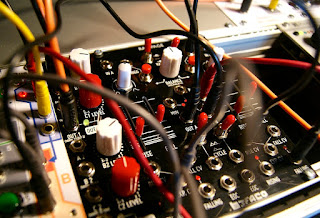
There were so many evolutions between the first family photo in September 2017 where my first modules are finally assembled in a 3U Eurorack synthesizer row beginning and now with almost two finished rows of 84HP.  The synth includes, from top to bottom from left to right, One ADSR envelope generator, one CV quantizer, two oscillators, two filters, four VCA, one phaser effect, one output module, one sample & hold with noise generator, one slew limiter, two attenuators, a mixer, a voltage reference, a double multiple, one chaotic modulation generator, a signal multiplier with CV offset, a double modulation generator, one random generator and a resonator.


First family photograph, September 2017 :


And nearly 3 years after....

Some of the big steps are detailed here below :

- my first module (August 2017 - built on November 2016) : you have to start somewhere


- the case (February 2018) : modules have a home now


- first kits (May 2018) : I now have nice modulation sources


- repairing my VCO (July 2018) : I finally have a tuned sound source


- Doepfer DIY (September 2018) : comes with my first filter


- Replacing the Doepfer DIY with separated elements (early 2020) : new ADSR, new VCO, new filter.


I learned a lot on this journey into the world of do-it-yourself synthesizers.
First of all, I improved my brazing technique.  I can now make denser builds than before.
I've learned how to design module panels.  I also tested and approved new suppliers, such as Thonk.
But more importantly I learned how to use the synthesizer, how to use it to create generative music, how to create different types of sounds.

I used the synthesizer to make 21 tracks.  Mostly as illustrations of the function of a module for the blog, but not only :
- 11 sound examples of the module at hand;
- 7 sound illustrations of the state of the synthesizer;
- 2 participations to the monthly KVR Music Cafe;
- 1 participation to Audiofanzine Inspired Composition (Compos Inspirées).


And here is the track of the day :


All sound from the modular synthesizer.  Too many tracks to detail them all. 
Most tracks were performed in a very traditional way for me : first writing and recording a MIDI track, then programming the synth sound and recording the audio using the Korg SQ-1 sequencer as a MIDI to CV converter.  Exceptions : drums were made using the SQ-1 as the sequencer and percussion were generated by the Turing Machine.
DAW : Reaper


Saturday, 30 May 2020

Sloth Chaos

Ready to be mounted in synth
In a chaotic system, tiny variations of the initial conditions lead to apparently random states of disorder.  A chaotic circuit in a modular synthesizer is the promise of slowly changing, never repeating ambient soundscapes.

This module produces two different, very slow, chaotic CV signals. It is my implementation of the Non Linear Circuits Sloth Chaos.  I chose the regular version with 1 cycle every 15-20 seconds.  Depending on component values, other versions include Apathy (about 1 minute), Super sloth (15-20 minutes) and Stasis (about 1.5 hour !).

I needed to accommodate the values to match what I have on my drawers.  I tested on a breadboard to see if little changes on some components values would make a difference.  It turned out that yes, it does make a big difference.  It looks like there is a pretty good balance between the feedback and the small signal, going to the integrator for the big signal.  The torpor potentiometer plays with that balance.  But go with 20% more or 20% less resistance on that path and you end up with either two synchronous, though out of phase and saturated signals, or two chaotic but very small signals.
Experimenting
The butterfly pattern on the oscilloscope is called a strange attractor (or Lorentz attractor) and is the plot of the two signals out of the circuit, each one on a different axis.  When the signals are roughly in synch they form an ellipsis.  Two wells of pseudo equilibrium are visible.  The signals spend a bit of time there before drifting apart.  None of this is predictable and highly depend on initial conditions.  Hence the chaotic nature of the circuit.

I did not have 91k resistors, 82k + 10k  would do the trick.  100k was too high, 82k too low.  Same with the 4.7M, replaced with 2x 2.2M.

I also made a small change in the original schematics.  I wanted to have the LED be less than a negative/positive indicator and follow the signal a bit more.  So I chose the output of the buffer after the small signal output instead of the output of the following opamp.

Layout
Adapted schematcis


Almost there

The main board is really cramped.  Those 1uF capacitors were bigger than expected.   I really had to be very cautious on some connections.  It's a little bit of a mess at times, but I'm quite happy with the result.


The two boards before assembly
Victory !

After some minor corrections to both the layout and the wiring of the boards, I finally got the familiar chaos attractor pattern on the oscilloscope. 

Torpor potentiometer does not have a lot of effect.  Tough it seems to me that the signals are spending more time around a stable state (i.e well) when the pot is maxed out.


Marking holes before drilling
Panel design is inspired by Clarke Robinson's panel with the small butterfly reminding of the popular view that even the minuscule disturbance of the air due to a butterfly flapping its wings in China can cause a hurricane in Texas


Bob cutting the hole for the potentiometer


And now a bit of sound.
We have here two saw waves originally in tune.  One of them detuned by Sloth small signal.
The filter cutt-off frequency is modulated by Sloth big signal.
Low Pass output goes to the phaser.
Band Pass output goes to Rings to Rings, modified by Sloth and output from sample & hold.

Rythmic gate from TAL Filter 2 and reverb from Voxengo OldSkollVerb in Reaper.

No VCA was harmed during the making of this piece.


This seems to put a close to the bottom row of the synth suitcase.
Synth suitcase bottom row

Sunday, 3 May 2020

Slew Limiter and Passive Attenuator

Next in line is a simple slew limiter associated to a passive attenuator.

Nothing fancy.  No CV control.  No choice of slope.

Finished module
When I removed my DIY-101 module, I lost the portamento on the oscillator.  Mind you, I seldom used it, because the VCO was not good enough. 
Nevertheless, it is an effect I fancy on an analog oscillator.


Bob drills the panel.
The slew limiter circuit is inspired by Yves Usson own Dual Gated Slew and the simple schematics from Synovatron.  Components value were constrained by what I had on my drawers at the time.

The attenuator is a simple passive one.


Layout and schematics

I changed the way I wired the panel.  In fact, I don't wire it anymore : pots and jacks are soldered on their own PCB, with the main board attached via spacers.  I'm not sure it spares connection wire but it is cleaner on the panel side : no more screw.  On the other hand, I have to be very accurate with my designs and my drilling.  I did three paper prototypes before finding the correct positioning of things.

Thonk proved a good resource to find the appropriate parts.


Assembled


Finally, here is a small sonic example.  The effect of the slew limiter on the pitch CV of the oscillators can be heard after 16 seconds.