Thursday 28 December 2017

Put a Rings on it.

If you like it, put a Rings on it, she said.

So I did.

I bought a Mutable Instruments Rings.

The module came this morning in a nice package, with a proper printed manual and a cool spinning top.


Rings arrived

Rings is a resonator : it simulates vibrating structures like strings, tubes or membranes.  It has a kind of polyphonic mode where a note is sustained, while the next is playing.  It can be excited by pretty much anything : envelope clicks, trigger pulses, noise or any other audio source.

My other planned modules are more into the traditional synth voice : VCO, VCA, VCF with some LFO and envelope generators.  So I think it will be a nice addition to the lot, especially as I want to go into some percussive sounds.

Rings installed in my temp rack


Now, I have a proper, thought very limited, synthesizer.

Here is a bit of sounds from the above patch.


The Sample & Hold clock is connected to the strumming input of the Rings, so notes will happen at the rate of the clock.
I choose the 4-voice polyphonic mode and the standard modal resonator.   I don't connect anything to the audio input, so this is the sound of the internal noise burst generator.  This gives a bell-like sound.
The brightness of the sound will be modified by the random voltage output of the random module.  The frequency will be modulated by the sample & hold output.  
First brightness and position are slowly increased.
Then I increase the clock rate while diminishing the damping.  And I finish by decreasing the rate and increasing the damping.


Saturday 30 September 2017

Panel technique

Concerning the module panels, I use Ray Wilson's techniques.

Working on the random module panel.
I decided to order two Doepfer 42HP (about 21 cm) blank panels.  They are not very expensive and they are the right height and the right thickness (2 mm).
One panel is dedicated to the DIY synth.  I should be able fit it on that size.
I cut the second blank panel with a good metal saw to have 3 panels of the desired sizes for my first modules.

It's doable but it's a pain.  And it's not easy to get them straight.
I'll try to stick to 4 or 8HP blank panels next time.   Using the large panel and my saw for larger sizes.

I use Inkscape to draw the panels.  It's open source.  A bit rough around the edge but overall quite powerful.  I print at least one intermediate version to test and two final versions : one with the indication for the holes and one with the final markings.


Locating holes

Holes are located thanks to a specific version of the panel drawing (in fact one of the drawing's layer), a punch and a hammer.
I then pierce them : 6-mm hole for jacks and LEDs, 8-mm hole for a potentiometer.  I use a 2-mm larger drill lightly to smooth the edges but you can use a step drill and insist a little.


Temporary annotated panel


I then try with the temporary paper version and I annotate all modifications.   This is my way to detect and correct the small imperfections.

Finally, when I'm happy with the final design, I laminate the paper template and I glue it on the aluminum panel.


I let some space outside the panel to be able to slide it to place.  Moreover I don't trust my ability with scissors.

Once dried up, I cut the excess with a sharp blade, using the edges of the panel as a ruler, and I start punching the holes with an precision knife.

Cutting holes
Removing excess of the laminated paper panel


Finally, it's time to put everything back into place.  Nuts and knobs gently hide the imperfections of the holes.

Details


Saturday 2 September 2017

First family photograph

You might have noticed that this blog is a little bit late with regards to the real progress of my synthesizer project.

This post is, for once, right on time.

My first 3 DIY Eurorack modules are now finished.
It's time for a family photograph...


And under the hood...


Friday 1 September 2017

Guitar effect in a Eurorack module

To add effects to my modular synthesiser, I had the idea to buy some guitar effect pedal kits and design the necessary adaptation circuit to include them in a Eurorack module.  One need some sort of adaptation to go from 12V to 9V power supply and to lower the audio signal level : from max 20Vpp to about 1 Vpp.   I reckon most pedals might take a line level input, so at least a ten-fold attenuation (-20 dB) was needed.

Final module : on the left, the pedal kit; on the right, the adaptation PCB.
I chose some kits from Das Musikding as I knew already they are high quality : a Chorus and a Phaser, as planned.
I decided to start with the Phaser.
Indeed, assembling the kit was a breeze. 

Then I started to design the adaptation circuit.

Breadboarding in progress.

My original idea was to have a simple dry-wet passive potentiometer with a buffer before and after.  But the attenuation in the middle position was too much.  It was good enough when used statically thanks to the boost of the second stage but you couldn't go smoothly from dry to wet.

Then I tried with having two different volumes knob, one for the dry signal, one for the wet signal and mix both.
But it wasn't the feel I was looking for.  I wanted a traditional dry-wet knob.

I finally stumbled upon this schematics from R.G. Keen.  It was spot on what I was looking for.

The three dry-wet topologies I tried.

Power supply side of the adaptation
The power supply uses a simple serial line regulator.  The implementation principles are very well explained on Sonelec website.  I chose to use an LM317 because I had some in my drawer.  These LM317 in TO92 package were a mistake in an order I made previously.  They were sitting in my drawer ever since as they can only draw 100mA.  Now is the time to put them into use.
A LM7809 would have been better suited for this job.   Some might even argue that the added components (3 resistors, 1 capacitor) are more expensive than an LM7809, but it's another story.


Cardboard panel prototype

 I wasn't too sure about the potentiometer and jack places on the panel.  So I made a cardboard mock up before punching holes in the aluminium panel.  I intend to use this technique later with the Doepfer DIY synth.  So I'd better learn.


Cabling in progress
I used PCB connectors for the link between the two PCB.
But this time, I opted to solder wires from the lower side of the PCB to the pots and jacks, instead of using  connectors. 
Note the plastic feet glued on top of the centre pot : the pedal PCB extended over it so I had to avoid unwanted contact between the two.

I cabled everything wrong at first : input on output, potentiometers the wrong way.  Every time it was possible to make a mistake, I did one.  It was a nice and clean way to connect the jacks and the pots the first time.  It was a pain to change afterwards.

Moreover, after having cabled everything, I had a more thorough look at the oscilloscope.  I decided to modify the circuit.  I removed the original 1uF capacitors in the signal path as they were eating all my low end.  Original schema might be nice for guitars, but not for the extended audio range of a synth.  I also added the compensation capacitors on both op amps, because they tended to oscillate.

Not easy to debug in this position.
Despite my early efforts on the breadboard, I didn't notice or take too seriously both behaviours.

Un-soldering and soldering parts with the circuit so tightly attached to the panel controls was a pain.  PCB connectors would have been handy.
I really need to make up my mind about them.


Final circuit and layouts are available here below.   This time, I correctly oriented the power connector.


I used Fritzing for the schematics because I thought it would permit me to smoothly go from schematics to breadboard layout.  Schematic capture is OK.  But the breadboard module is not as usable as DIYLC, so I ended up using the latter for the layout.

A bit of work for the panel marking …


… and here is the finalised module.


A word about the gain staging to finish. 
I intended to have the first stage to go from -40dB (/100) to -20dB (/10).  From R.G. Keen, I gathered that the panner circuit would divide roughly by 3 (or -10 dB) and the 51k feedback resistor of the output op amp would give an initial  x3.41 gain.  I designed the output stage to have a final maximum gain of + 37 dB (x70). This way I could more or less cover the level drop by the first stage and the panner.   I indicated +30 dB on the panel to take into account the -10dB from the panner and it looked cooler than +27 dB.

Measurement confirmed my hypothesis.
At the highest settings, with a 10Vpp input, full dry, the output stage saturated gently.  Expected : at maximum gain, the circuit would go a bit higher than 22 Vpp
But when the output stage was at minimum gain, I expected a voltage drop of -40 dB : down to 100mVpp.  I saw … 0 V at the output.   Strange.  I certainly once again overlooked a detail.

Anyway, I have more than enough gain dynamics.  I was fed up with debugging this circuit.  That would do for now.  I updated the front panel to acknowledge that particular behaviour.

Monday 28 August 2017

Yusynth's Random Module.

This is the story of my build of a Yusynth's Random Module in Eurorack format.

I learned a lot by building this.  Read :  "I made a lot of mistakes."
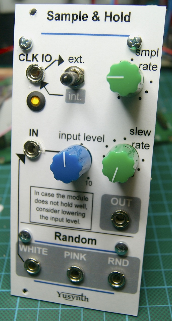
Finished module
I started from the schematics from Yusynth website.  It is clear and quite well explained.

Once again, I patiently captured the layout in DIYLC.  I used Yves' own layouts to guide me. 
I chose to make the two PCB version, one on top of the other, as I was sure one PCB would be too large for the Eurorack format.

I added two reverse polarity protection diodes.  And I chose Schottky diodes this time, to limit the voltage drop.

Anyway, I reproduced the mistake of having the power connector horizontally and not vertically.  Certainly due to the fact it was oriented that way in Yves'  layouts.
Here are the layout I used.

The layout of the two boards
I was mistaken in one of my part order and ordered some 2-Watt 10 Ohms resistors.   Nothing wrong done, as I had enough space to accommodate them, but they are total overkill.

Work-in-progress
As I was soldering the parts, I scrupulously followed each and every wire and parts, highlighting the schematics and my layout at the same time.


Despite those efforts, nothing worked at first.  Except the white noise output seemed to output ... some noise.

I quickly diagnosed that the oscillator did not oscillate.
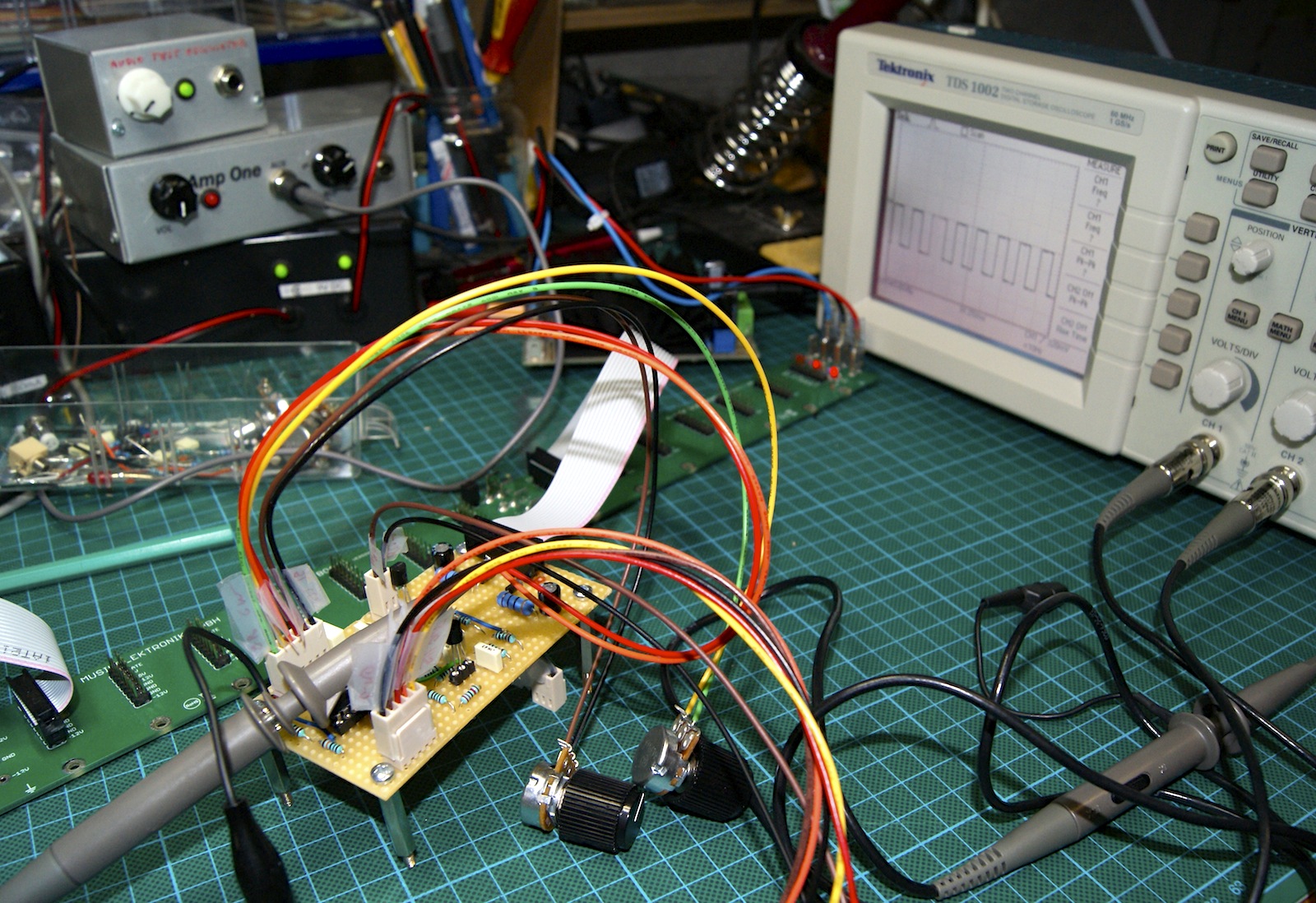
Board inspection found nothing.  Without an oscilloscope, I was blind.  You cannot debug by ear a non audible LFO.

I finally bought a used Tektronik oscilloscope.  It confirmed the diagnostic, but still, no clue.
Oh, what's this ?  An unconnected pin on R5 ?
Soldered.  First problem fixed.

Oscillator debugging.  First success.
I began inspecting each output systematically and saw nothing at the random output.
It uses the pink noise output as reference.  And nothing on the pink noise output as well.
A wrong connection this time, due a misleading layout : because of the bad layout drawing, it was not clear which pin of the Q4 transistor to connect R20.  Of course, it was clear to me at layout time but I chose the wrong one at solder time.

Now white, pink and random outputs seemed to work.  More on this later on.

The sample&hold did not to hold.

Not holding properly
I couldn't understand why.
I reproduced the circuit on a breadboard with spare parts, so that I could better debug it and learn how it works.

Part of the circuit on a breadboard
I could reproduce the behavior : not holding well with signals from the noise module : white or random, while the circuit hold well with other signals. 
I switched capacitors, changed resistors, exchanged transistors to not avail.

Out of idea, I gave up and asked Google about it.
Finally, the solution was given by Yves Usson himself.  In a forum he detailed why it might not work :
Here are the possible causes for a holding fault :
- too high white noise signal (>8Vpp)
- a dead BF245C (Q5)
- a dead TL072 (U2)
- a dead diode (D3)
The last three could be excluded as the circuit behaved properly with another (about 1Vpp) input signal and I had the same behavior after having reproduced the circuit on the breadboard.  So dead components were out of the question.

Noise source was effectively way too high : about 20Vpp.  
In fact, noise saturated both output opamps so R34 and R27 should have been lowered.  I didn't want to lower my noise sources as much as 8Vpp, so I chose a compromise.
I chose R34 and R27 as 220k, both because hasty measure and crude calculation would give me about 16Vpp and I had some in my drawers.

As the circuit seems to be sensitive to the input voltage, I decided to add a passive attenuator on the input.

More debugging


Finally, my Random module works as expected.
It took some time and effort but the journey was worth it.


And it does a little bit more than blinking its LED...


Thursday 17 August 2017

My first DIY module

Start small they say.

My first DIY Eurorack module is a simple DC mixer.

I made that choice because I reckon it's easy to build and I found tons of examples on the Net.  It can serve the purpose to mix any type of signals, CV and audio.

Schematic was inspired by Yusynth's with some tips from Ken Stone's and Dintree websites.  It's not much, but you have to start somewhere.

Schematic capture on DIYLC


You'll notice that the first stage is at unity gain and I chose to have the second stage with a 2x gain so that I can use the circuit to boost the signal if need be.

I used DIY Layout Creator (DIYLC for short) to capture the schematic and to trace the layout for a perf board.    Layout is OK, but capturing the schema was a pain.

Layout of the simple mixer : power at the bottom, inputs on the left, outputs on the right..
Warning : the schematic and layout are given for illustration purpose only.  Use them wisely and at your own risk.  Don't forget that I don't really know what I'm doing.

I used a lot of space.  It's a luxury I won't have anymore for the next modules.

I did a mistake though in placing the power connector parallel to the bottom side of the module.  It seemed a good idea at first to have the power lines aligned with the IC.  But once placed into the rack, the flat cable will be crooked.  I didn't respect the de-facto standard to have the -12V at the bottom.  My bad.

Before finalising the cabling, I assembled the mechanical parts to check if all fit.

Recto

Verso


I  then started with the cabling that did not concern the board : herebelow the input attenuators. 

Cabling pots


I chose to have PCB connectors on the board to ease with the mounting and un-mounting.  I did it on the next module as well.  It takes a lot of space and does not bring so many advantages I think.  My third module will be different.  I'm still undecided on this.

Fully assembled

Here is my first DIY Eurorack module, alongside the A-110-1 VCO and the next one : the Sample & Hold and Random module from the inspiring project from Yves Usson.   The two DIY modules have a temporary annotated paper facade.

The first three


Saturday 12 August 2017

Do I really look like a guy with a plan ?

Nowadays, as you start a project like a modular synthesizer, you look for resources on line.  You are soon overwhelmed by the possibilities.
It's easy to get drowned into the 'mare modulae'.  In a pinch, you imagine a system that will take dozens of modules and require tons of space and money, with little purpose.

So it's important to remind the fundamentals :
  • start small.
  • some sort of a plan is necessary.


I intend to go one step at a time, at a steady pace; leapfrogging from stable state to another stable state to have some fun and learn at each phase.

With a modular synth, I believe it's a good idea to start planning with the type of sounds you have in mind. 

I tried to imagine my first patches.  How many modulation sources will I need to achieve a fluid ambient patch ?  How many mixer tracks for a drum machine ? Do I need to input a guitar into my FX setup ?  What could be the minimal viable system that permits me to achieve my goal ?

My plan for a modular synthesizer came after I made some rough sketches about two simple synthesizers I thought I could build as first Synth DIY projects.

At first, I wanted to build a noise machine, with some whizz, some bangs, some crsssshh.  Something different from the sound of my Anushri.  I intended to build it all with the help of the schematic from the Yusynth project.   I wasn't too sure of my ability to tune a VCO though.  So I was happy that this project didn't involve tuned VCO.  The main sound source was  a noise generator, plus a couple of VC-LFO that could eventually extend to audible range.

Early sketch of the noise box

Then, I thought I could build after that a basic synth with roughly the same sound architecture as a Roland SH-101.  Nothing revolutionary.  But I would have built it myself, once again thanks to the resources from the Yusynth project.

Is it really simple ?

When I saw that both projects shared the same basic functions, I decided to merge them in a single modular synth.  The Eurorack format seems the most practical and has a great community.  I settled for 2x 84HP rows, partially because Doepfer sells a simple kit to start with.

So here we are.

I'm still not very confident to build and tune a complete VCO, plus I needed a good example of Eurorack module to serve as mechanical reference.  I chose a Doepfer A110-1 Standard VCO as my first and main VCO.
To bootstrap myself on the basic synth voice, I picked a Doepfer DIY synth.  The assembled board has all the necessary functions : VCO-VCF-VCA + Enveloppe generator & LFO.  I intend to fit it in a semi-modular 42HP module.

The Doepfer boys chilling on the bench.

Time to think about something to build from scratch.

I'll give a go at the Sample&Hold/Random module from Yusynth (for the noise source).
Regarding effects, I want to try mounting regular guitar pedal kits into Eurorack format.
Finally, I plan some utilities (multiples, inputs, outputs, inverters, …) in a 2U space between the two rows.
And as a starter, a simple module : a basic audio/CV mixer.

Early case sketches

I wanted to experiment by making the case myself as well.  After having sketched several versions of angular cases : 30°-45°-60°, 0°-30°-60°, etc… , I finally decided to keep it simple and have a basic 8U box.


Basic plan of the basic 8U case

White modules are in the making.  They constitute the minimal viable synth depicted above.   When I'll be there, we'll see.  Greyed out modules are envisaged later on, depending on what I feel is missing.

I'll still need some kind of controller or sequencer though.  A Korg SQ-1 or an Arturia Beatstep maybe.

Mmmh let's dive into more demo video....


Friday 4 August 2017

DIY Synth Kit : Mutable Instruments Anushri

Here we are.  At last.  I built my first synthesizer on November 2013 (was it 4 years ago ?).
I chose an Anushri kit from Mutable Instruments.

The first part of the kit.
Hairy !!

The kit was perfect.  Very easy to solder, even with the high number of parts (100 ?  200 ?).
Metallised holes, complete kit, detailed and incremental assembly instructions, even a victory candy.  A very professional product.

As everything went smooth from unpacking to final assembly, I do not have a lot to tell.  The important thing I learned was to pace myself : not planning everything in one sitting, building small portions at a time, being very focused, carefully following the instructions.  It took a bit of time.  I think it was the key to achieve the assembly without an itch.

Resistors went first.

Finally, the only problem I have is that I'm not able to correctly tune it on more than two octaves.  I have to rely on the embedded automatic tuner.  It's fine but it means I can not use the CV in and out to integrate the synth in a modular system.  I have to rely on MIDI then.

The two boards ...  finished


Close-up


The Victory Candy in the last bag of parts.


Anushri ... alive.

 If you want to know how it sounds, here is a short (30 seconds) demo I made :


All sounds from the Anushri (including the drums).
Use of the built-in generative drum machine and arpegiator.
Yes : there are tons of effects on top of the bare sound of the synth.

By building ready to assemble kits, you learn a lot about soldering, about the different parts that compose a synthesizer.  They usually come with full schematics and tips on how to debug.  This is helpful if you want to dig into the details and understand what's inside the hood.

Unfortunately,  Mutable doesn't do DIY kits anymore.  Some of their products (namely the Shruti) can still be found at TubeOhm's, albeit under the name Phoenix due to copyright reasons : http://www.tubeohm.com/TubeOhm/INTRO_HARDWARE.html

There are a lot of other synthesizer kits out there.  For example :

Paia Fatman ( http://www.paia.com/fatman.asp ) is one of the most renown.

PreeFM2 ( http://ixox.fr/preenfm2/ ) is a small DIY FM synthesizer, DX7 compatible.

Bastl instruments ( http://www.bastl-instruments.com/diy/ ), Synthrotek ( http://www.synthrotek.com/) and Erica Synth ( http://ericasynths.lv/en/home/ ) have a nice collection of DIY Eurorack modules kits.