Showing posts with label passive. Show all posts

Friday, 28 May 2021

Passive Modules

Finished guys
It looks like it has been a year since I built my last DIY module.
Time for some passive modules I guess.

I ordered two 2-hp blank.  I needed another multiple to fill the rack and I decided to experiment with some passive functions.


A passive multiple is very basic.  You simple connect the tip and ground of each jack.  In practice the ground connection is established via the aluminium panel.  No need to use wire.

The main difficulty here is at 2-hp, or a bit more than 1 cm width, you do not have a lot of margin to drill your holes.  You do not want the body of the jack to go over the edge.
Not perfect but good enough.
I used mostly very cheap jacks I got a long time ago, except for the one with the switch as the switch on the cheaper ones is really terrible.

Behind the scene


Bob at work with the panel
I also experimented with some minimal panel marking by using my Dremel to carve some traces and fill them with a permanent marker.  This should not age very well. Time will tell.

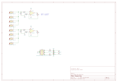
The second module is the combination of a passive OR and a half-wave rectifier, ideal to combine gates and manipulate control voltages or distord audio.  You’ll find  the layout for both of them at the end of the article.  I got the schematics from unrecordings! blog

In the rack

In the following piece, the Korg SQ-1 produces two tracks of gates and CV for the kick and hi-hat.
I used the multiple to distribute the gates everywhere in the synth and I used the OR function to build a third melodic track from the first one and the output of the Turing Machine,  clocked by the second track.  I know it sounds complicated.  Patch schematics is at the end of the article.
The half-wave rectifier produces some overtones to spice up the sounds.
The variations in the piece is me playing with the sequencer.


Connection layout


Patch of the day

Friday, 6 April 2018

Passive attenuator and reference voltage

This module combines in 4HP some utilities I first planned for a 2U utility panel.

Finished module chilling on bench


From top to bottom : a passive attenuator, two reference voltages and a manual gate.

The attenuator and the gate are normalled to the 10V reference voltage.

The reference voltage electronic schematic is scavenged from the same function in Mutable Instrument Shades.   Hence the reference to Olivier Gillet, whose work is a great source of inspiration for me.


Ongoing panel assembly


Some of the components are soldered on the panel.
I hesitated to include the 51 ohms protection resistors at the op-amps outputs.  Maybe I should have put them inside the feedback loop of the op-amps ...  Nevertheless, the  circuit was built when I thought I might add them and I did not want to  ruined my earlier work, so they ended up on the panel.


The op-amp went into smoke as soon as I began the first test : I had inverted the -12 V and + 12 V pins.  :-(
I resorted to solve it with some trace removal and a couple of wires.

Problems solved.

So no layout this time : i'm too ashamed.  :-/
Still, here is the final electrical schematic.

Passive Attenuator and Reference Voltage


Monday, 2 April 2018

The next DIY modules

My next two DIY modules are simple utilities.

The two circuits in progress
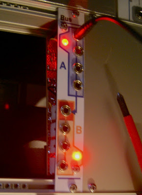
I started with a passive multiple.  I called it 'bus module', somehow inspired by the CV bus from Make Noise.

Finished bus module


Nothing special here.

The jacks are cabled in parallel in two groups of four, the second one is normalled to the first one. 

Without a plug in the first jack of the B bus, the module behaves as a 1:6 multiple.  And with the plug in, the module is two 1:3 passive multiples (or two bus of 4 entries).


Bus module verso

So if it is passive, what is the electronic circuit for ?

The small electronic circuit is used to visualize the signal that flow through the module via two LEDs, one for each group.  They are red/green LEDs, green shows the positive side of the signal, red the negative side.  I got that idea from the Make Noise's CV bus.  The implementation is inspired from Mutable Instrument's Links.


Layout

Schematics


The second module will be the subject of the next post.

In the mean time, let's see if the beast is alive...