 |
| The two circuits in progress |
 |
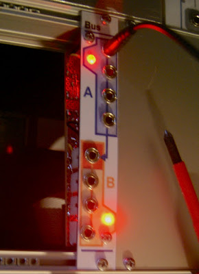
| Finished bus module |
Nothing special here.
The jacks are cabled in parallel in two groups of four, the second one is normalled to the first one.
Without a plug in the first jack of the B bus, the module behaves as a 1:6 multiple. And with the plug in, the module is two 1:3 passive multiples (or two bus of 4 entries).
 |
| Bus module verso |
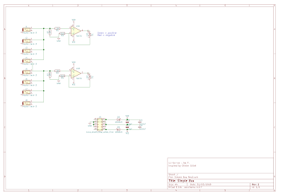
So if it is passive, what is the electronic circuit for ?
The small electronic circuit is used to visualize the signal that flow through the module via two LEDs, one for each group. They are red/green LEDs, green shows the positive side of the signal, red the negative side. I got that idea from the Make Noise's CV bus. The implementation is inspired from Mutable Instrument's Links.
 |
| Layout |
 |
| Schematics |
The second module will be the subject of the next post.
In the mean time, let's see if the beast is alive...

No comments:
Post a Comment