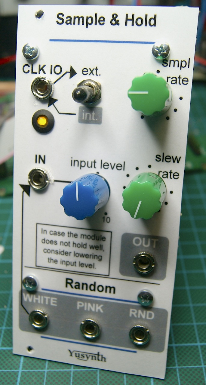
This is the story of my build of a
Yusynth's Random Module in Eurorack format.
I learned a lot by building this. Read : "I made a lot of mistakes."
 |
| Finished module |
I started from the schematics from
Yusynth website. It is clear and quite well explained.
Once again, I patiently captured the layout in
DIYLC. I used Yves' own layouts to guide me.
I chose to make the two PCB version, one on top of the other, as I was sure one PCB would be too large for the Eurorack format.
I added two reverse polarity protection diodes. And I chose Schottky diodes this time, to limit the voltage drop.
Anyway, I reproduced the mistake of having the power connector horizontally and not vertically. Certainly due to the fact it was oriented that way in Yves' layouts.
Here are the layout I used.
 |
| The layout of the two boards |
|
I was mistaken in one of my part order and ordered some 2-Watt 10 Ohms resistors. Nothing wrong done, as I had enough space to accommodate them, but they are total overkill.
 |
| Work-in-progress |
As I was soldering the parts, I scrupulously followed each and every wire and parts, highlighting the schematics and my layout at the same time.
Despite those efforts, nothing worked at first. Except the white noise output seemed to output ... some noise.
I quickly diagnosed that the oscillator did not oscillate.
Board inspection found nothing. Without an oscilloscope, I was blind. You cannot debug by ear a non audible LFO.
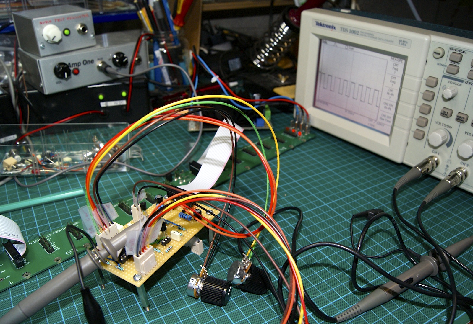
I finally bought a used Tektronik oscilloscope. It confirmed the diagnostic, but still, no clue.
Oh, what's this ? An unconnected pin on R5 ?
Soldered. First problem fixed.
 |
| Oscillator debugging. First success. |
I began inspecting each output systematically and saw nothing at the random output.
It uses the pink noise output as reference. And nothing on the pink noise output as well.
A wrong connection this time, due a misleading layout : because of the bad layout drawing, it was not clear which pin of the Q4 transistor to connect R20. Of course, it was clear to me at layout time but I chose the wrong one at solder time.
Now white, pink and random outputs seemed to work. More on this later on.
The sample&hold did not to hold.
 |
| Not holding properly |
I couldn't understand why.
I reproduced the circuit on a breadboard with spare parts, so that I could better debug it and learn how it works.
 |
| Part of the circuit on a breadboard |
I could reproduce the behavior : not holding well with signals from the noise module : white or random, while the circuit hold well with other signals.
I switched capacitors, changed resistors, exchanged transistors to not avail.
Out of idea, I gave up and asked Google about it.
Finally, the solution was given by Yves Usson himself. In a forum he detailed why it might not work :
Here are the possible causes for a holding fault :
- too high white noise signal (>8Vpp)
- a dead BF245C (Q5)
- a dead TL072 (U2)
- a dead diode (D3)
The last three could be excluded as the circuit behaved properly with another (about 1Vpp) input signal and I had the same behavior after having reproduced the circuit on the breadboard. So dead components were out of the question.
Noise source was effectively way too high : about 20Vpp.
In fact, noise saturated both output opamps so R34 and R27 should have been lowered. I didn't want to lower my noise sources as much as 8Vpp, so I chose a compromise.
I chose R34 and R27 as 220k, both because hasty measure and crude calculation would give me about 16Vpp and I had some in my drawers.
As the circuit seems to be sensitive to the input voltage, I decided to add a passive attenuator on the input.
 |
| More debugging |
Finally, my Random module works as expected.
It took some time and effort but the journey was worth it.
And it does a little bit more than blinking its LED...