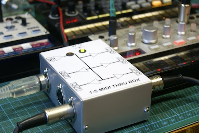
Finally, I closed the lid on the MIDI Thru Box I was working on for a loooong time.
Not that it was particularly difficult. I really was a slacker on this project.
 |
| Testing the finished product |
 | ||
| Validation on the breadboard. |
 |
| Printed Board Assembly |
I chose to slightly modify the original to have 5 outputs out of the 6 inverting Schmitt trigger of the 74HC14. The input LED indicator is driven by a transistor.
As I wanted to power the circuit with a standard pedal power supply (9V - center negative), the circuit has its own 5V voltage regulation.
 |
| Bob cleans the mess during drilling |
Circuit assembly went like a breeze.
Drilling the box needed a bit of attention with the small M3 holes next to the big ones for MIDI jacks.
 |
| Drill box |
 |
| Inside |
I didn't see how I could test it without putting everything in its final place. I really was worried about a possible debugging session.
My poor ESI MIDI interface gave me the creeps as I was testing.
But finally, all went fine and I found no mistake to correct.
 |
| Testing with a couple of Korg Volcas |
As promised, the full schematics :

No comments:
Post a Comment