Moreover, using 6.35 mm jacks is more practical to interface with external gears than keeping 3.5 mm jack.
 | ||
| My output module |
I got inspired by Make Noise's Rosie : cross fader between A and B inputs, send and return functions and the attenuation stage to match line level.
Make Noise chose to have the levels of the send-return at modular level, to use with effects in the modular synth itself (like their own reverb module). I decided to go with variable attenuation and gain in the send-return path to be able to use it with external effects like guitar pedals.
As a result, the return jack can still be used as a third potential input for the module, but it might need some attenuation beforehand in order to match the levels of the A-B inputs.
 |
| Messing around on the breadboard |
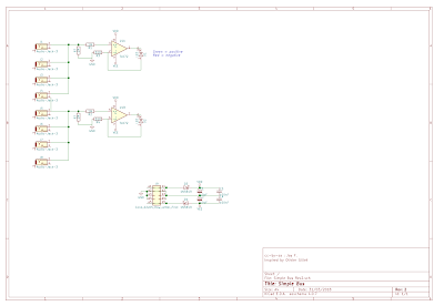
The electric schematic is an assembly of three circuits, with slight modifications.
 |
| Ouput module electrical schematics |
First, the crossfader at the input comes from the panner schematic from R.G. Keen. I modified the resistors value to match the resistors and the potentiometer I already had.
Second, the output stage is the output stage from Dintree Output mixer. I removed the R69 resistor to better match my target output level.
Third, the send-return circuits are Ken Stone's stomp box adapter with variable attenuation and gain. I removed the 10uF capacitor in the return feedback loop as it created an potentially audible high pass filter at minimum gain.
 |
| Finished circuit on the bench |
And here is the final layout. I had to correct a couple of slight mistakes but other than that it went smoothly.
 |
| The layout |
I elaborated my gain chain to have +4dBu (around 1.7 V peak signal), if I enter a 5 V peak signal on one input and keep level potentiometer at two third.
As there are three op-amps in the audio loop, I made sure they were all in an non-inverting configuration to avoid phase inversion.
I added a peak detector as a simple comparator followed by a rectifier, a filter and the diode. Classic. This will detect peaks above 5 V (or 5 dB below the +18dBu clipping level) on the positive side only, but that will do.
Why this value ? I first decided for a much lower 1.8 V peak. But I reckoned it was far too low and that I should target a value around +12 dBu. I decided to change a single resistor and I only have that 15k instead of the needed 12k.
If you're interested in the relationships between V, Vrms, dBu, dBV, I found this very useful website : http://www.sengpielaudio.com/calculator-db-volt.htm
 |
| View from the back |
 |
| Ongoing panel |
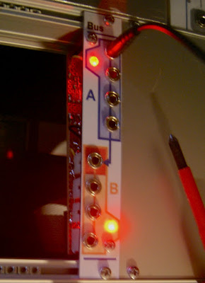
The panel is one of the most cramped I had to do.
Notice the small id tag denoting this is my 20th DIY project.
 |
| Wire mess |
Wiring was a mess.
8 HP was a fine choice. But for the future, I have to resist the temptation to cram as much function as possible into the available space.
I first wanted more vintage look knob caps, but they were too large and I switched back to traditional copies of Davies 1900H.
Finally, here it is in it's natural habitat.
 |
| Final view |


